A 4–20 mA current loop is a measurement circuit based on the 4–20 mA analog signal to feed the component sensors and transmitters.
The 4–20 mA standard came about in the 1950s with the rise of electronic controllers and instrumentation to replace the 3–15 psi pneumatic standard. In the 1980s, the manufacturer Emerson pushed for the Highway Addressable Remote Transducer (HART) communication protocol, which is used to transmit digital information overlaid on the 4–20 mA signal without interfering with that signal.
Today, 4–20 mA communication is the typical interval used by a control system for analog signal acquisition and is so common that it has become a standard in industry. The 4–20 mA standard came about mainly from:
- the need to transport analog signals from sensors to PLCs and from PLCs to actuators;
- the difference in the analog signals generated by sensors and those to be sent to the actuators;
- the need for signal standardization.
The 4–20 mA standard is based on current signal encoding and takes advantage of the fact that an analog signal represented by an electrical current is less sensitive to noise than a signal represented by voltage.
To function, a current loop needs the voltage coming from a sensor to first be converted into a proportionate current, where 4 mA represents the zero-level output of the sensor and 20 mA represents the sensor’s full-scale output. Measurements between the maximum and minimum values indicate that the circuit is controlling the sensor or the actuator. Verification of a 4–20 mA loop includes a test of the output of the transmitter, the wiring, the input fault detection of the control system, and the return wiring from the transmitter.
In a common two-wire 4–20 mA connection between the transmitter and the receiver, the (typically 24–30 V) DC power supply is almost never available in the transmitter.
The connection diagram shows the advantage of encoding the minimum current value (4 mA). In the event of failure (e.g. transmitter malfunction or line interruption), a value of 0 mA is converted into 0 V, which allows for detection.
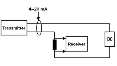
Diagram of a 4–20 mA current loop
Industrial uses
The 4–20 mA current loop is a common method of transmitting sensor information in many applications of monitoring industrial processes, typically in systems that monitor pressure, temperature, pH, flow, or other physical factors.
In industrial instrumentation, current loops bring benefits in terms of signal precision that is not influenced by a drop in voltage in the conductors. A current loop typically includes a sensor, a transmitter, a receiver, an ADC, or a microcontroller. The transmitters are generally loop-powered, two-wire transmitters in which the circuit does not require separate power cables and which can be installed near the sensor, resulting in lower costs and power consumption.
A current loop can also be used to control a positioner, an actuator, or a device that is intrinsically more immune to noise. Current signals are intrinsically more immune than voltage signals to the sort of electromagnetic interference (EMI) that is highly common in industrial settings, particularly over long distances.
Another reason for the success of the 4–20 mA standard is the fact that the current flow regulated by the transmitter is the same at any point in the current loop. In addition, wire failures have a lower impact given that an interrupted wire in a current loop generates a current of 0 mA. Last but not least, it is possible to program most current transmitters so as to regulate out-of-range current in the event of a sensor malfunction. For all of these reasons, 4–20 mA loops are ideal for use in noisy industrial settings in which the signal may be transmitted over long distances and data may be sent to remote locations.