There is an important link between SRS (Safety Requirement Specification) and safety loops. Specification defines SIS (Safety Instrumented System) architecture which includes safety loops, from the sensor to the final element.
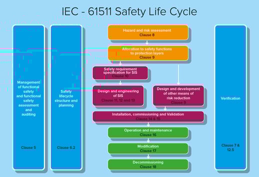
In the process industry, the international standard IEC 61511 sets out the engineering of E/E/PE (electrical, electronic, or programmable electronic) safety systems. The standard addresses safety management for the entire life cycle of a system, from designing to decommissioning. Fundamental for this approach is the overall safety life cycle which describes activities related to the specification, development, operation, and maintenance of a SIS system. The safety validation plan of a SIS system provides the schedule to validate the SIS system in relation to the SRS and other information, such as causes and effects tables. Validation includes all major operational processes (startup, shutdown, maintenance, irregular conditions, etc.), procedures, techniques and measures to be used, plan, personnel, and related departments. It also includes validation planning for safety application software.
Within the life cycle, in the initial hazard and risks assessment phase, the goal is to determine hazardous events of the process and associated equipment, the events’ sequence leading to a hazard, requirements and safety functions for risks reduction. In addition to probabilistic calculation models, the method of determining SIL levels can be through risks charts, particularly if risks to be analyzed are quite a few. Risks’ charts and risks’ matrixes can be very useful, especially when used as a preliminary and quick technique to filter out all except the highest SIL levels. However, careful calibration of the techniques used should avoid erroneous results.
Protection and redundancy level analysis
Layers of Protection Analysis (LOPA) is a structured way to calculate risk layer reduction and SIL levels. It is conducted in a similar way to that of the HAZOP (HAZard and OPerability analysis) one. Potential hazards are generally identified through the HAZOP approach and imported into the LOPA worksheets, thus maintaining a traceable link between the two analyses, from hazard identification to risk reduction requirement and targeted SIL. LOPA approach results generally show that hazardous situations have safety consequences that can be protected with a given SIF function. In addition to or as an alternative, some practical tables can be used to compare the main SIS architectures, with different redundancy types, as the main parameters affecting SIL change, such as the SIS subsystems diagnostic coverage and recurring tests range. Controllers commonly used in process industry are generally complex systems and only PLC hardware is covered by a declaration of conformity to standards; but also accessories, I/O, barriers, interposing relays, and terminal blocks with associated wiring must be equally compliant and suitable for the required safety level.
Risk analysis and management
Since a risk must be quantified in terms of both consequences and probability of occurrence, it is appropriate to rank it on a numerical scale where the larger the number, the greater the impact or probability of occurrence. Generally speaking, a risk matrix allows risk prioritization and assessment. Each life cycle phase describes an activity and each activity requires inputs. Each phase consists of an activity which should have documented procedures and that generates information as output for subsequent phases. This scheme requires listing the required information as input for the activity and the information generated by the activity as output for the next step. Although the standard describes life cycle stages and information requirements for each of them, some of the stages and their associated documents may be combined. Activities should be performed in the most efficient way and information presented in the clearest manner. The last phase output generally consists of a HAZOP study and risk analysis to identify safety function requirements and risk reduction targets.
SIL level of each SIF function is selected during the SIL level determination study using the risk graph, LOPA analysis, or risk matrix. This information must be communicated to the responsible team through the Safety Requirements Specification (SRS) to ensure that, during implementation, the project meets SIF safety integrity requirements. Alarms associated with a given Probability of Failure on Demand (PFD) can significantly reduce the frequency of incidents by achieving a Risk Reduction Factor (RRF) of 1/PFD. It is useful to remember that, mathematically, the PFD is a probability and therefore a dimensionless quantity, with a value between 0 and 1.
Would you like to know more? Watch our webinar “SRS, how to define a safety loop?" at GMI YouTube channel