In data-acquisition systems, a multiplexer may be defined as a circuit or device that selects and combines multiple input signals into a single output line.
The signal generated by the transducers of a data-acquisition system is generally not suited to direct processing by the unit that generates a control algorithm. There normally needs to be a signal-processing stage in which all the operations needed to properly transmit the signal are executed. Measurement also entails directly storing data in the memory of a numeric processor.
The conditioned signal typically undergoes frequency-division multiplexing (FDM) or time-division multiplexing (TDM). In the latter of these, connection of the outputs of the various chains to the system’s memory is sequential, i.e. in a predetermined order.
In each measuring chain, the analog signals are transformed into digital signals by an analog-to-digital converter (ADC) and then encoded according to the representation of the value of the magnitude and adapted to the amplitude range (programmed amplification).
In controlled industrial processes, there are usually dozens of sensors, so it is not cost effective to reserve a dedicated system of data acquisition — including amplification, A/D conversion, etc. — for each signal. This is why data acquisition calls for a signal multiplexing stage at input into a single acquisition channel, which is implemented by way of specific devices known as multiplexers.
Definition
A multiplexer is a system of multiple inputs and just one output to receive signals coming from multiple acquisition networks. The device transfers all input signals to a microprocessor, which receives and processes the data, transmits it to the output devices, and controls the system as a whole.
With multiplexing, a measuring system is able to sequentially channel multiple signals to a single digital converter, thereby providing a low-cost means of increasing the number of channels of the system. A multiplexer consists of a set of switches and provides a significant cost reduction by making use of just one A/D converter for multiple inputs. As such, a multiplexer may be considered a circuit or device that makes it possible to share the available capacity of a single connection between multiple transmission channels.
By way of selector pins, one and only one input is allowed to communicate with the only output. The control unit scans all inputs in sequence and reads them at a speed that respects the sampling theorem for the given signal.
In essence, multiplexers are used to increase the quantity of data that can be transmitted over a network with a given bandwidth over a given period of time.
Types
There are multiplexers for both digital and analog signals. A digital multiplexer has digital input signals coming from multiple data-acquisition networks. The device transfers these input signals to a processing system, typically a microprocessor, which receives and processes the data, transmits it to the output devices, and controls the system as a whole. An analog multiplexer is a device that makes it possible to commute n analog channels into a single analog output channel. This commutation is controlled by a digital signal that encodes the input channel to be selected. An analog multiplexer may be single-ended or handle differential inputs. In a single-ended multiplexer, the device is set up to commute individual analog channels, whereas a differential multiplexer may be used for differential signals.
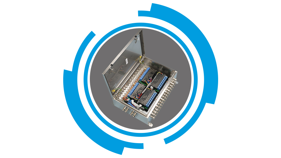
G.M. International D2000 Intrinsically Safe Multiplexing System is available for digital or temperature field applications. More specifically, the series includes a gateway unit (D2050M), 16-input expansion boards to receive temperatures from thermocouples, RTDs, mV or mA signals (D2010M, D2011M), a 32-input digital expansion board (D2030M), and signal repeaters with SPDT relay outputs (D2052M) or with open-collector outputs (D2053M).
In typical applications, the gateway (D2050M) installed in the safe zone offers 2-wire intrinsically safe communication, supplying the I/O boards (D2010M, D2011M, D2030M) with both the signal and the power. Positioned near the sensors, these I/O boards acquire and transmit the data to the gateway, which then sends a fieldbus (redundant Modbus) or serial (RS232) output signal to a PLC/DCS in the safe zone. The cost savings in wiring and on-board I/O boards of the control unit are substantial, combined with optimization of the system of data acquisition.